

Online Brochure
Vortex Cell Specifications and Calibration
Free Radical EO - Key Points
The destruction of pathogens and recalcitrant organics via free-radical driven Electrochemical Oxidation (EO) is a complex and relatively young field. Stepwise degradation of large complex and highly stable organic molecules involves many competing reactions, some of which are thermodynamically limited and others kinetically limited. All are centered on efficiently matching highly energetic free radicals with the targeted and often highly-stable, chemical bonds.
At its core there are 3 key processes in play:
Generating OH (and other free radicals) and stabilizing them such that they are available to react with target bonds. This is where our Ebonex® and EboNext® anodes offer unique advantages. Unlike conventional catalytic anode surfaces, OH radicals will evolve and become attached to Ebonex® or EboNext® under aqueous anodic conditions. This effectively preserves what are otherwise extremely short-lived reagents, long enough to be of practical use in EO.
Transporting typically slow-moving high molecular weight target species to the OH free radicals attached to an Ebonex® or EboNext® anode. This is primarily driven by concentration of the target species and its byproducts, electrolyser residence time and the level of shear within the electrolyte.
Importantly, Electrolyte Shear can be critically important (and is often overlooked) in transporting relatively immobile and often dilute target molecules. This is a core feature of the Vortex Cell, where the level of vorticity (shear) in the electrolyte can be controlled and its effect on reaction kinetics evaluated.
Vortex Cell
Our Vortex Cell is primarily intended to characterize free-radical based Electrochemical Oxidation (EO), over a broad range of potential process streams and during the stepwise degradation of those. This is the essential first step in the effective development of design and operating criteria for full-scale treatment processes.
We developed our cell to generate performance data across a broad range of target species and water chemistries, by varying the 3 key parameters, anodic current density, reaction chamber dwell time, and electrolyte shear (vortex mixing).
It is NOT intended to be the optimal treatment configuration for any specific waste stream.
It IS intended to generate comparative performance data across both target species and during the stepwise degradation of those species.
NOTE: The optimal ranges of current density, electrolyte shear (vortex mixing) and cell residence time may vary across target species (and feed stream chemistries) AND the stage in a target species’ degradation.
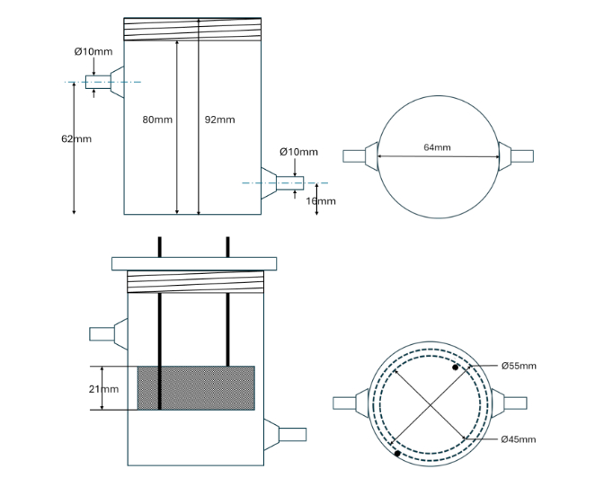
Electrodes
Grade 1 Ti mesh 50% void fraction, with EboNext® P500 coating.
Operating Range: Anode CD operating range for characterization – 5-50mA/cm2.
Outer electrode: Ø55mm x 20mm with 50% void fraction = 18.14cm2.
o Max anodic current = 907mA.
Inner electrode: Ø45mm x 20mm with 50% void fraction = 14.84cm2.
o Max anodic current = 742mA.
Electrode gap ~4mm.
Solution: Vortex Characterisation Cell
Introducing the first EO Characterisation Cell developed to unlock EO efficiency for waste stream variabilities. Our characterisation cell provides rapid qualitative analysis of the relative importance of shear, residence time and concentration variations for PFAS destruction rates.
Objectives: Qualitative characterization of Mass Transport v Diffusion during EO.
Characterise your PFAS waste streams, so you can select the best electrolyser.
Evaluate and select the best performing electrodes from our expanding range of Ebonex® and EboNext® Andersson-Magneli Phase materials and coatings.
Characterise waste stream variability in real-time.
Manage PFAS mineralization rates of your EO process.
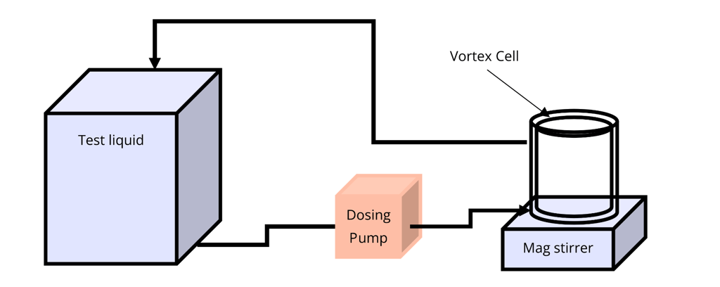
Typical Characterisation Set-Up
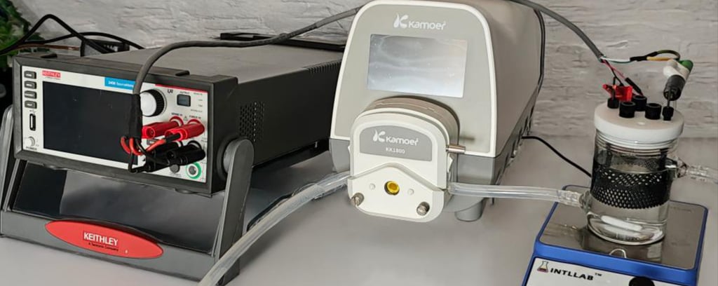
Our Vortex Cells are intended to be used as the electrochemical reactor in a bench scale characterization system consisting of at least:
Calibrated power source or Potentiostat capable of outputting 1-2A and 0-20V.
Adjustable magnetic stirring platen.
Calibrated peristaltic pump.
Thermocouple.
Containers for liquid to be treated, supporting recirculating and/or pass-through operation.
The diagram below shows a simplified flow circuit set-up for recirculation mode. Then the following image shows a minimum level, installation.
Heat Management
Requirements for electrolyte and/or cell temperature management will depend largely on the overall volume of liquid used in a study.
At the maximum recommended current setting of 50mA/cm2, the cell will generate approximately 8W of heat, or 480J per minute of operation. Assuming no heat losses, this is sufficient to heat 200ml of electrolyte contained in the cell by 1K in ~2min. For a closed volume of electrolyte this is significant, and a temperature-controlled water bath could be required to maintain the temperature withing desired limits for tests running longer than 10-20 minutes.
However, in recirculating mode with a 5.0l electrolyte reservoir, the same 8W would require ~45minutes to raise the electrolyte temperature by 1K, which is potentially within the losses due to black body radiation. In such a case heat management may be of little benefit.
Characterization Overview
Bench scale characterization is the starting point to a significant chemical engineering exercise that would culminate in trade-off analyses of process equipment, operating parameters, reliability etc., expressed in terms of capital costs, operating efficiency, operating costs, etc.
The purpose of the Vortex cell is to support this larger exercise by determining the optimal electrolyser type for full-scale operation, and its target operating parameters.
For large-scale processes with controlled and repeatable inputs, a comprehensive optimization program is often appropriate. Extensive characterization testing can be used to develop and plot 3-dimensional surfaces of specific contaminant destruction per unit of energy (e.g. Mol/J, kg/Wh) versus current density, residence time (a function of the flow into and out of the cell) and level of electrolyte shear (mixing).
For ad-hoc water treatment applications where inputs and contaminants are likely to be highly variable, a less exhaustive approach which delivers a qualitative evaluation of EO destruction of a target species with respect to residence time, electrolyte shear and current density is a useful starting point.
Care and Maintenance
Ebonex® and EboNext® electrodes are reversible and periodic current reversal (typically every 10-20 minutes) is recommended to maintain the electrode surfaces free of any deposits.
Operation under constant current is preferred as the current density of the Anode is a primary driver of EO reaction kinetics.
The two electrodes are of different size and surface area. Therefore, the current set-point, needs to be based on the polarization of the cell.
The cell has been configured to operate at an Anodic current density of 1-50mA/cm2 for process characterization. The upper limit of 50mA/cm2 is equivalent to:
907mA when the outer electrode is anodic and
742mA when the inner electrode in anodic.
Always ensure that both electrodes are fully submerged in electrolyte before and whenever they are energized.
Avoid operating the cell with a vortex of such force that it entrains copious amounts of air, as this will result in a partially dry electrode condition and invalidate the measurement of current density.
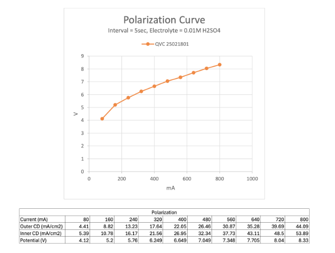
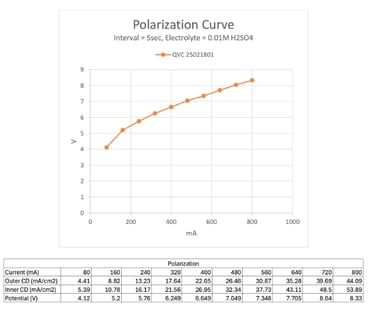
Polarisation Curve
The outer electrode set as the anode and voltage stepped up in ten 5 second increments to achieve 10 incremental current settings between 80 and 800mA for a current density range of 4,41-42.99mA/cm2.
Stirring was activated throughout, sufficient to generate a mild vortex with no entrained air. The electrolyte temperature was 25C.
The potential required to achieve and maintain each current set point measured at the end of each 5 second increment and plotted below.
Acronyms clarified
PFAS (Per- and polyfluoroalkyl substances)
DWI (Drinking Water Inspectorate)
EA (Environment Agency)
CAPEX (Capital Expenditure)
OPEX (Operational Expenditure)
PFD (Process Flow Diagram)
P&ID (Piping and Instrumentation Diagram)
IX (Ion Exchange)
AEOP (Advanced Electrochemical Oxidation Process)
GAC (Granular Activated Carbon)
ESA (Environmental Site Assessment)


Take Action
Address
London, United Kingdom
Contact
Copyright © 2026 2Encapsulate Limited. All rights reserved.
Useful Links
Social Media
Website built by ricardon.co.uk
Company number: 14883182